

Boolean algebra is the mathematical foundation of all digital computing. Every operation a processor performs (comparing values, making decisions, storing data) can be described by combinations of just three basic logical operations. In this article, we explore this algebra from scratch: from the fundamental operations to the theorems, from De Morgan’s laws to the simplification of circuits, with practical Python examples along the way.
The introduction to this series reminded us that all the hardware of a computer, deep down, understands only two states: zero or one. Before opening up the memory and the processor, we start there: with the mathematics that manipulates these two values and with which all the circuits of the machine are described.
Historical context #
In 1854, the English mathematician George Boole published An Investigation of the Laws of Thought, in which he proposed an algebraic system to represent and manipulate logical propositions using the values 0 (false) and 1 (true). Boole did not have computers in mind: he was formalizing logical reasoning in mathematical terms.
Almost a century later, in 1937, Claude Shannon realized that Boolean algebra could model electrical switching circuits. In his convention, which measures the impedance of the circuit, an open circuit corresponds to 1 and a closed one to 0, and so a series connection is a sum and a parallel connection is a product. In this article we use the opposite convention, which is more intuitive for switches and lamps: 1 is a closed circuit (the current flows and the lamp lights up) and 0 is an open circuit, so that series becomes AND and parallel becomes OR. With that, Boolean algebra came to be used to design circuits.
The idea is in the master’s thesis that Shannon wrote at MIT, A Symbolic Analysis of Relay and Switching Circuits, available in the institute’s open repository and summarized in a paper published in 1938. It is often remembered as the most important master’s thesis of the 20th century: the psychologist Howard Gardner described it as “possibly the most important, and also the most famous” of the century.
If you have studied propositional logic, you will recognize the operations. The difference is in the emphasis: while propositional logic focuses on formal reasoning, Boolean algebra focuses on algebraic manipulation and implementation in circuits. See the article Logic for programmers for an introduction to propositional logic.
Variables and logical functions #
A Boolean variable (or logical variable) can only take two values: 0 (false) and 1 (true). A Boolean function takes one or more Boolean variables as input and produces a Boolean output.
The same logical function can be represented in four equivalent ways:
- Algebraic expression: compact notation using mathematical operators
- Truth table: lists all \(2^n\) possible combinations of \(n\) variables and the corresponding output
- Logic symbol (logic gate): graphical representation used in circuit diagrams
- Equivalent electrical circuit: implementation with switches and components
For a function with \(n\) variables, the truth table has \(2^n\) rows. With 2 variables: 4 rows. With 3 variables: 8 rows. With 10 variables: 1,024 rows.
Example: the function \(F(A,B) = \bar{A} \cdot B + A \cdot \bar{B}\) can be represented algebraically, as we have just seen, in a truth table:
| A | B | \(\bar{A} \cdot B + A \cdot \bar{B}\) |
|---|---|---|
| 0 | 0 | 0 |
| 0 | 1 | 1 |
| 1 | 0 | 1 |
| 1 | 1 | 0 |
Or as a logic symbol (the symbol \(\oplus\), an XOR gate, which we will see shortly), or as an equivalent electrical circuit. The four representations describe exactly the same behavior.
Fundamental operations #
The three basic operations of Boolean algebra are enough to describe any logical function. In fact, only two are needed: the sets \(\{\text{AND}, \text{NOT}\}\) and \(\{\text{OR}, \text{NOT}\}\) are functionally complete, that is, any other operation can be built from them. This concept will be developed in detail after De Morgan’s laws.
AND: Logical product #
$$F(A, B, C, \ldots, N) = A \cdot B \cdot C \cdots N$$\(F = 1\) if and only if all inputs are 1. For two variables:
| A | B | \(F = A \cdot B\) |
|---|---|---|
| 0 | 0 | 0 |
| 0 | 1 | 0 |
| 1 | 0 | 0 |
| 1 | 1 | 1 |
For three variables, the truth table has \(2^3 = 8\) rows:
| A | B | C | \(F = A \cdot B \cdot C\) |
|---|---|---|---|
| 0 | 0 | 0 | 0 |
| 0 | 0 | 1 | 0 |
| 0 | 1 | 0 | 0 |
| 0 | 1 | 1 | 0 |
| 1 | 0 | 0 | 0 |
| 1 | 0 | 1 | 0 |
| 1 | 1 | 0 | 0 |
| 1 | 1 | 1 | 1 |
Only the last row, when all inputs are 1, results in 1.
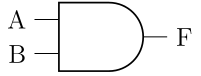
The figure below shows the graphical symbol of the AND gate, used in digital circuit diagrams:
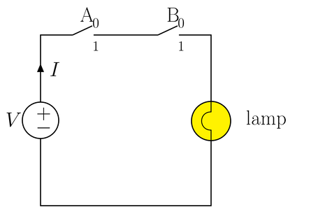
Electrical analogy: AND is equivalent to switches in series, and the lamp only lights up if all the switches are closed, since the current has to pass through each one of them. The figure below illustrates this concept:
In Python, the AND operation exists in two forms:
# Logical operator (for booleans, evaluates with short-circuiting)
True and True    # True
True and False   # False
False and True   # False  ← does not even evaluate the second operand

# Bitwise operator (for integers, operates bit by bit)
0b1010 & 0b1100  # 0b1000 = 8
5 & 3            # 1  (0101 & 0011 = 0001)
and vs & in Python
and is the logical operator: it returns one of the operands (not necessarily
True/False) and uses short-circuit evaluation. & is the bitwise
operator: it operates on each pair of corresponding bits of two integers.
We have already covered short-circuit evaluation here before. Likewise, we have seen the bitwise operators in another article.
OR: Logical sum #
$$F(A, B, C, \ldots, N) = A + B + C + \cdots + N$$\(F = 1\) if at least one input is 1. For two variables:
| A | B | \(F = A + B\) |
|---|---|---|
| 0 | 0 | 0 |
| 0 | 1 | 1 |
| 1 | 0 | 1 |
| 1 | 1 | 1 |
For three variables:
| A | B | C | \(F = A + B + C\) |
|---|---|---|---|
| 0 | 0 | 0 | 0 |
| 0 | 0 | 1 | 1 |
| 0 | 1 | 0 | 1 |
| 0 | 1 | 1 | 1 |
| 1 | 0 | 0 | 1 |
| 1 | 0 | 1 | 1 |
| 1 | 1 | 0 | 1 |
| 1 | 1 | 1 | 1 |
Only the first row, when all inputs are 0, results in 0.
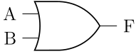
The figure below shows the graphical symbol of the OR gate, used in digital circuit diagrams:
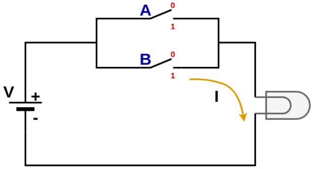
Electrical analogy: OR is equivalent to switches in parallel, and the lamp lights up if any switch is closed. The figure below illustrates this concept:
In Python, the OR operation also exists in two forms:
# Logical operator
True or False    # True
False or False   # False

# Bitwise operator
0b1010 | 0b1100  # 0b1110 = 14
5 | 3            # 7  (0101 | 0011 = 0111)
NOT: Logical negation #
$$F(A) = \bar{A}$$It simply inverts the input: \(F = 0\) if \(A = 1\), and \(F = 1\) if \(A = 0\).
| A | \(F = \bar{A}\) |
|---|---|
| 0 | 1 |
| 1 | 0 |
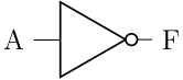
NOT is also written as \(A^{\prime}\) or \(\sim A\). In the logic symbol, the small circle (bubble) at the output indicates inversion.
The figure below shows the graphical symbol of the NOT gate, used in digital circuit diagrams:
In Python, inversion exists in two forms:
# Logical operator
not True    # False
not False   # True

# Bitwise operator (bit complement — result depends on the size of the type)
~5          # -6  (two's complement in signed integers)
~0b0101     # ...11111010 (in two's complement)

# To work with positive bits, use a mask:
~5 & 0xFF   # 250  (0b11111010)
Derived functions #
The next three functions are derived from the fundamental operations. The first two (NAND and NOR) are especially important for circuit manufacturing.
NAND: NOT AND #
$$F(A, B, \ldots, N) = \overline{A \cdot B \cdots N}$$\(F = 0\) if and only if all inputs are 1 (complement of AND).
| A | B | \(F = \overline{A \cdot B}\) |
|---|---|---|
| 0 | 0 | 1 |
| 0 | 1 | 1 |
| 1 | 0 | 1 |
| 1 | 1 | 0 |
NAND is one of the cheapest gates to manufacture in CMOS technology (Complementary Metal-Oxide-Semiconductor, the dominant standard in the manufacturing of integrated circuits). We will see later that this has a fundamental consequence for chip design.
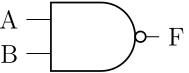
The figure below shows the graphical symbol of the NAND gate, used in digital circuit diagrams:
We can define the NAND function in Python using the basic logical operations:
def nand(a, b):
    return not (a and b)

nand(True, True)   # False
nand(True, False)  # True
nand(False, True)  # True
nand(False, False) # True
NOR: NOT OR #
$$F(A, B, \ldots, N) = \overline{A + B + \cdots + N}$$\(F = 1\) if and only if all inputs are 0 (complement of OR).
| A | B | \(F = \overline{A + B}\) |
|---|---|---|
| 0 | 0 | 1 |
| 0 | 1 | 0 |
| 1 | 0 | 0 |
| 1 | 1 | 0 |
Like NAND, the NOR gate takes up minimal silicon area in CMOS. For this reason, both are widely preferred in chip manufacturing, a reason we will explore in detail later.
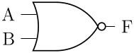
The figure below shows the graphical symbol of the NOR gate, used in digital circuit diagrams:
We can define the NOR function in Python using the basic logical operations:
def nor(a, b):
    return not (a or b)

nor(False, False)  # True
nor(True, False)   # False
XOR: Exclusive OR #
$$F(A, B) = A \oplus B = A \cdot \bar{B} + \bar{A} \cdot B$$\(F = 1\) when exactly one of the inputs is 1 (different inputs).
| A | B | \(F = A \oplus B\) |
|---|---|---|
| 0 | 0 | 0 |
| 0 | 1 | 1 |
| 1 | 0 | 1 |
| 1 | 1 | 0 |
XOR is 1 when the number of inputs equal to 1 is odd. It is the basis of parity detection circuits and of the binary half adder, which we build shortly.
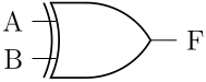
The figure below shows the graphical symbol of the XOR gate, used in digital circuit diagrams:
Examples in Python:
# Bitwise XOR operator
5 ^ 3     # 6  (0101 ^ 0011 = 0110)
True ^ True   # False (1 ^ 1 = 0)
True ^ False  # True  (1 ^ 0 = 1)

# Interesting property: A ^ A = 0, A ^ 0 = A
x = 42
x ^ x     # 0   (any value XOR itself = 0)
x ^ 0 # 42 (any value XOR 0 = itself)XOR has two useful symmetry properties when manipulating expressions:
- Inverting both inputs does not change the output: \(A \oplus B = \bar{A} \oplus \bar{B}\)
- Inverting only one input inverts the output: \(A \oplus \bar{B} = \overline{A \oplus B}\)
As an exercise, try to prove these identities using the definition \(A \oplus B = A\bar{B} + \bar{A}B\) together with De Morgan’s laws.
Comparison table of the 6 gates #
The table below gathers the essential characteristics of the six gates studied:
| Gate | Expression | Output = 1 when… | Universality |
|---|---|---|---|
| AND | \(A \cdot B\) | All inputs = 1 | No |
| OR | \(A + B\) | At least one input = 1 | No |
| NOT | \(\bar{A}\) | Input = 0 | No |
| NAND | \(\overline{A \cdot B}\) | Not all inputs = 1 | Yes |
| NOR | \(\overline{A + B}\) | No input = 1 | Yes |
| XOR | \(A \oplus B\) | Different inputs | No |
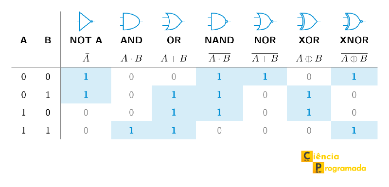
For quick reference, the figure below gathers in a single truth table the outputs of all the gates for the four combinations of \(A\) and \(B\). It includes XNOR, the complement of XOR (output 1 when the inputs are equal), which appears in Exercise 2 further on and returns in the next article:
The diagram below highlights the derivation relationships: NAND and NOR result from applying NOT to the output of AND and OR, respectively; XOR is OR without the case in which both inputs are 1, that is, \(A \oplus B = (A + B) \cdot \overline{A \cdot B}\):
graph TD
    subgraph Básicas["Basic operations"]
        AND["AND: A·B
F=1 if all=1"]
        OR["OR: A+B
F=1 if any=1"]
        NOT["NOT: Ā
Inverts the input"]
    end
    subgraph Derivadas["Derived"]
        NAND["NAND: NOT(A·B)
F=0 if all=1"]
        NOR["NOR: NOT(A+B)
F=1 if all=0"]
        XOR["XOR: A⊕B
F=1 if inputs differ"]
    end
    AND -->|NOT at the output| NAND
    OR  -->|NOT at the output| NOR
    OR  -->|"without the case A = B = 1"| XOR
First application: the half adder #
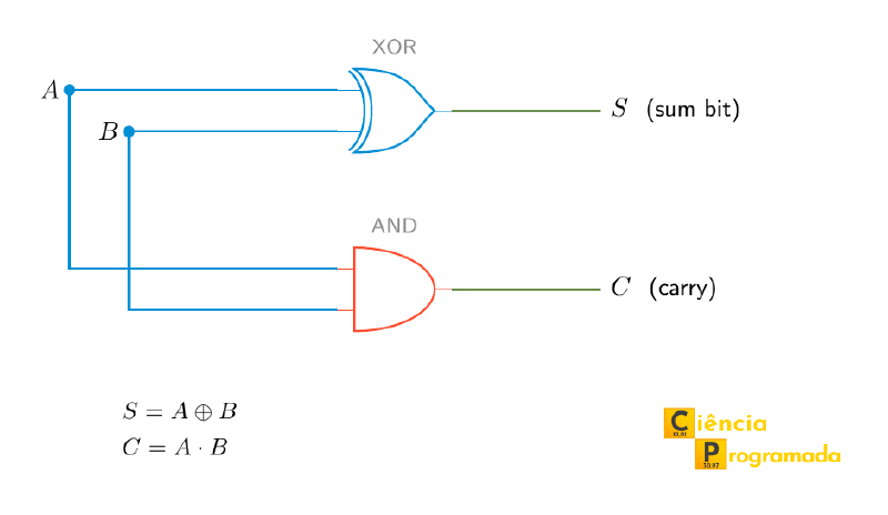
With just two of the gates seen so far, we can already build the first arithmetic circuit. Adding two bits \(A\) and \(B\) produces two outputs: the sum bit, \(S\), and the carry, \(C\), which only appears when \(1 + 1 = 10_2\):
| A | B | \(C\) (carry) | \(S\) (sum) |
|---|---|---|---|
| 0 | 0 | 0 | 0 |
| 0 | 1 | 0 | 1 |
| 1 | 0 | 0 | 1 |
| 1 | 1 | 1 | 0 |
The \(S\) column is exactly the truth table of XOR, and the \(C\) column is that of AND:
$$S = A \oplus B \qquad C = A \cdot B$$This circuit is called a half adder. The figure below shows how it is assembled: the same two inputs feed an XOR, which generates the sum bit, and an AND, which generates the carry.
In Python, with the bitwise operators:
def half_adder(a, b):
    """Adds two bits and returns (carry, sum)."""
    return a & b, a ^ b

for a in (0, 1):
    for b in (0, 1):
        print(a, b, half_adder(a, b))
# 0 0 (0, 0)
# 0 1 (0, 1)
# 1 0 (0, 1)
# 1 1 (1, 0)
The “half” in the name comes from what is missing: the half adder has no input for the carry coming from the previous column, so it only works for the least significant bit. Putting two of them together with an OR gives the full adder, which adds three bits. It is in Computer Arithmetic: Addition and Subtraction and returns in this series inside the ALU of the hypothetical processor, where several full adders lined up add whole words. The variants used in real processors, such as the carry-lookahead adder, are covered in the entry Adder (electronics).
Postulates of Boolean algebra #
Postulates are the basic rules accepted without formal proof. They form the basis on which all theorems and properties are built.
| # | Postulate | AND form (·) | OR form (+) |
|---|---|---|---|
| 1 | Binary variable | \(A \in \{0, 1\}\) | \(A \in \{0, 1\}\) |
| 2 | Constant with 0 | \(0 \cdot 0 = 0\) | \(0 + 0 = 0\) |
| 3 | Constant with 1 | \(1 \cdot 1 = 1\) | \(1 + 1 = 1\) |
| 4 | Mixed | \(1 \cdot 0 = 0\) | \(1 + 0 = 1\) |
| 5 | Complement | \(\bar{1} = 0\) | \(\bar{0} = 1\) |
Note the duality: in general, swapping AND for OR and 0 for 1 (and vice versa) gives another valid postulate. This symmetry repeats throughout the system.
Theorems #
Theorems are consequences derived from the postulates:
| # | Theorem | AND form (·) | OR form (+) | Name |
|---|---|---|---|---|
| 1 | \(A \cdot 0 = 0\) | \(A + 0 = A\) | Absorbing / identity element | |
| 2 | \(A \cdot 1 = A\) | \(A + 1 = 1\) | Identity / absorbing element | |
| 3 | \(A \cdot A = A\) | \(A + A = A\) | Idempotence | |
| 4 | \(A \cdot \bar{A} = 0\) | \(A + \bar{A} = 1\) | Complement | |
| 5 | \(\bar{\bar{A}} = A\) | \(\bar{\bar{A}} = A\) | Double negation | |
| 6 | \(A(A+B) = A\) | \(A + AB = A\) | Absorption | |
| 7 | \(A(\bar{A}+B) = AB\) | \(A + \bar{A}B = A + B\) | Expanded absorption |
Note in Theorems 1 and 2 that the roles of 0 and 1 swap depending on the mathematical operation:
- In the AND operation (\(\cdot\)), 1 is the identity element (\(A \cdot 1 = A\)) and 0 is the absorbing element (\(A \cdot 0 = 0\), the output is forced to zero).
- In the OR operation (\(+\)), 0 is the identity element (\(A + 0 = A\)) and 1 is the absorbing element (\(A + 1 = 1\), the output is forced to one).
Python check: idempotence and complement
# Idempotence: A & A = A, A | A = A
for a in (0, 1):
    assert (a & a) == a, f"Failed for a={a}"
    assert (a | a) == a, f"Failed for a={a}"

# Complement: A & ~A = 0, A | ~A = 1 (for 1 bit)
for a in (0, 1):
    complement = 1 - a  # 1-bit complement
    assert (a & complement) == 0
    assert (a | complement) == 1

print("All theorems verified!")
Algebraic properties #
The following properties govern how the operators behave when we combine multiple variables with one another: they are the essential tools for manipulating and simplifying Boolean expressions.
Commutative #
$$A \cdot B = B \cdot A \qquad A + B = B + A$$The order of the operands does not change the result, just like in ordinary multiplication and addition.
Associative #
$$A \cdot (B \cdot C) = (A \cdot B) \cdot C$$$$A + (B + C) = (A + B) + C$$
The grouping does not matter: we can omit parentheses in sequences of AND or of OR.
Distributive #
$$A \cdot (B + C) = A \cdot B + A \cdot C$$This one is analogous to the distributivity of multiplication over addition in ordinary algebra. But Boolean algebra has a second distributive form with no equivalent in ordinary algebra:
$$A + (B \cdot C) = (A + B) \cdot (A + C)$$
Proof of the distributivity of OR
$$= A + AC + AB + BC \quad \text{(idempotence: }A \cdot A = A\text{)}$$
$$= A(1 + C + B) + BC$$
$$= A \cdot 1 + BC \quad \text{(absorbing element: }1 + X = 1\text{)}$$
$$= A + BC \quad \checkmark$$
De Morgan’s laws #
De Morgan’s laws are the most important theorems for manipulating and simplifying Boolean expressions. They are named after Augustus De Morgan (1806 to 1871), a British mathematician, friend and correspondent of Boole since 1842. The two published their books on logic in 1847, almost at the same time: Formal Logic, by De Morgan, and The Mathematical Analysis of Logic, by Boole. Similar relations were already known to medieval logicians, such as William of Ockham, but it was De Morgan who stated them in the language of formal logic that we use today. In Boolean notation:
$$\overline{A + B + C + \cdots + N} = \bar{A} \cdot \bar{B} \cdot \bar{C} \cdots \bar{N}$$
Mnemonic rule: “Break the bar, flip the operation (· becomes +, + becomes ·), invert each variable.”
Tabular proof for two variables #
First law: \(\overline{A \cdot B} = \bar{A} + \bar{B}\)
| A | B | \(\bar{A}\) | \(\bar{B}\) | \(\overline{A \cdot B}\) | \(\bar{A} + \bar{B}\) |
|---|---|---|---|---|---|
| 0 | 0 | 1 | 1 | 1 | 1 ✓ |
| 0 | 1 | 1 | 0 | 1 | 1 ✓ |
| 1 | 0 | 0 | 1 | 1 | 1 ✓ |
| 1 | 1 | 0 | 0 | 0 | 0 ✓ |
In a circuit, the first law says that a NAND has the same output as an OR with both inputs inverted, as the figure below shows:

Second law: \(\overline{A + B} = \bar{A} \cdot \bar{B}\)
| A | B | \(\bar{A}\) | \(\bar{B}\) | \(\overline{A + B}\) | \(\bar{A} \cdot \bar{B}\) |
|---|---|---|---|---|---|
| 0 | 0 | 1 | 1 | 1 | 1 ✓ |
| 0 | 1 | 1 | 0 | 0 | 0 ✓ |
| 1 | 0 | 0 | 1 | 0 | 0 ✓ |
| 1 | 1 | 0 | 0 | 0 | 0 ✓ |
Likewise, the second law says that a NOR is equivalent to an AND with inverted inputs:

Circuit equivalences #
De Morgan’s laws reveal four ways to implement each gate using combinations of other gates. This is fundamental for standardizing designs using only NAND or only NOR:
| Equivalence | Expression | Reading |
|---|---|---|
| 1 | \(\overline{AB} = \bar{A}+\bar{B}\) | NAND(A,B) = OR with inverted inputs |
| 2 | \(\overline{A+B} = \bar{A}\cdot\bar{B}\) | NOR(A,B) = AND with inverted inputs |
| 3 | \(A \cdot B = \overline{\bar{A}+\bar{B}}\) | AND(A,B) = NOR with inverted inputs |
| 4 | \(A + B = \overline{\bar{A}\cdot\bar{B}}\) | OR(A,B) = NAND with inverted inputs |
Equivalences 1 and 2 were already shown as equivalent logic circuits in the previous section. Equivalences 3 and 4 can be seen in the two figures below:


In CMOS technology, NAND and NOR gates take up less silicon area than AND and OR. With De Morgan’s equivalences, any design can be implemented using only one type of gate, which simplifies manufacturing.
# Checking De Morgan in Python with bitwise operators
def de_morgan_1(a, b):
    """NOT(A AND B) must equal (NOT A) OR (NOT B)"""
    left_side = ~(a & b)
    right_side = (~a) | (~b)
    return left_side == right_side

def de_morgan_2(a, b):
    """NOT(A OR B) must equal (NOT A) AND (NOT B)"""
    left_side = ~(a | b)
    right_side = (~a) & (~b)
    return left_side == right_side

# Check for all 1-bit values
for a in (0, 1):
    for b in (0, 1):
        assert de_morgan_1(a, b), f"De Morgan 1 failed: a={a}, b={b}"
        assert de_morgan_2(a, b), f"De Morgan 2 failed: a={a}, b={b}"

print("De Morgan's laws verified for 1 bit!")
Universality of gates (functional completeness) #
The NAND and NOR gates, besides being cheap to manufacture, have a remarkable property: each of them is functionally complete on its own. This means that, with an unlimited supply of just one of these types of gate, it is possible to rebuild any other logic gate and, consequently, any digital circuit.
In principle, this property allows building complex chips with billions of identical components (for example, NAND gates in CMOS technology), although real chips use libraries with several types of gate.
Building the basic logic with NAND #
To prove the functional completeness of NAND (\(\overline{A \cdot B}\)), see how it can take the role of the three fundamental operations:
-
NOT from NAND: Just tie the two inputs of the NAND gate together. By the idempotence law (\(A \cdot A = A\)), the output will be the negation of the input.
$$F = \overline{A \cdot A} = \bar{A}$$ -
AND from NAND: Since NAND is an “inverted AND”, just invert its output using a second NAND configured as NOT.
$$F = \overline{(\overline{A \cdot B}) \cdot (\overline{A \cdot B})} = A \cdot B$$ -
OR from NAND: By De Morgan’s laws (\(\overline{A \cdot B} = \bar{A} + \bar{B}\)), we invert the inputs individually before passing them through a third NAND gate.
$$F = \overline{\bar{A} \cdot \bar{B}} = \bar{\bar{A}} + \bar{\bar{B}} = A + B$$
Try to do the same exercise using only NOR gates. The reasoning is analogous, starting from the duality of Boolean algebra (presented in the Postulates section): how would you build a NOT, an OR and an AND using only the function \(\overline{A+B}\)?
Solution to the challenge: basic logic with NOR
Like NAND, the NOR gate (\(\overline{A + B}\)) is also functionally complete. The construction logic mirrors that of NAND, thanks to the duality of Boolean algebra:
-
NOT from NOR: We tie the two inputs together. By the idempotence law (\(A + A = A\)), the output will be the negation of the input.
$$F = \overline{A + A} = \bar{A}$$ -
OR from NOR: Since NOR is an “inverted OR”, just invert its output using a second NOR configured as NOT (as in step 1).
$$F = \overline{(\overline{A + B}) + (\overline{A + B})} = A + B$$ -
AND from NOR: By De Morgan’s second law (\(\overline{A + B} = \bar{A} \cdot \bar{B}\)), we invert the inputs \(A\) and \(B\) individually (using NORs as inverters) and feed the result to a third NOR gate.
$$F = \overline{\bar{A} + \bar{B}} = \bar{\bar{A}} \cdot \bar{\bar{B}} = A \cdot B$$
Simplifying logical expressions #
Why simplify? #
Simpler expressions correspond to circuits with fewer logic gates, which means:
- Lower manufacturing cost (fewer components)
- Higher speed (fewer propagation delays)
- Lower power consumption
Simplification uses the postulates and theorems of the algebra to rewrite an expression in an equivalent form, but with fewer terms or variables.
Worked examples #
The following examples progressively apply the tools seen so far, from simple properties to the Consensus Theorem, showing the algebraic reasoning step by step:
Example 1: Distributive property of OR
Show that \(A + BC = (A + B)(A + C)\)
$$(A+B)(A+C) = AA + AC + AB + BC$$$$= A + AC + AB + BC \quad \text{(idempotence)}$$
$$= A(1 + C + B) + BC$$
$$= A + BC \quad \checkmark \quad \text{(absorbing element: } 1 + X = 1\text{)}$$
Example 2: Expanded absorption
Show that \(A + \bar{A}B = A + B\)
$$A + \bar{A}B = A + AB + \bar{A}B \quad \text{(absorption: } A = A + AB\text{)}$$$$= A + B(A + \bar{A})$$
$$= A + B \cdot 1 = A + B \quad \checkmark$$
Example 3: Simplification with three variables
Simplify \(F(x,y,z) = \bar{x}yz + x\bar{y}z + xy\bar{z} + xyz\)
$$F = \bar{x}yz + x\bar{y}z + xy(\bar{z} + z)$$$$= \bar{x}yz + x\bar{y}z + xy \quad \text{(complement: } \bar{z} + z = 1\text{)}$$
$$= y(\bar{x}z + x) + x\bar{y}z$$
$$\text{Applying expanded absorption with } A=x, B=z: \quad \bar{x}z + x = x + z$$
$$= y(x + z) + x\bar{y}z = xy + yz + x\bar{y}z$$
$$= yz + x(y + \bar{y}z) = yz + x(y + z) \quad \text{(expanded absorption again)}$$
$$\boxed{F(x,y,z) = xy + xz + yz}$$
The result \(xy + xz + yz\) is the majority voter function for 3 variables: the output is 1 when at least 2 of the 3 inputs are 1.
It is also, exactly, the carry of a full adder. Replacing \(x, y, z\) with the bits \(A\), \(B\) and the carry coming from the previous column, \(C_{in}\), we get \(C_{out} = AB + AC_{in} + BC_{in}\): there is a carry whenever at least two of the three bits being added are 1. The full adder appears, written as \(AB + C_{in}(A \oplus B)\) (the same function), in Computer Arithmetic: Addition and Subtraction, and returns in this series inside the ALU of the hypothetical processor.
Example 4: Consensus Theorem
Show that \(AB + \bar{A}C + BC = AB + \bar{A}C\)
The term \(BC\) is redundant, because every combination that makes it 1 is already covered by the other two terms:
- When \(A = 1\): \(BC\) is only 1 if \(B = C = 1\), but \(AB\) already covers that case.
- When \(A = 0\): \(BC\) is only 1 if \(B = C = 1\), but \(\bar{A}C\) already covers that case.
Formally:
$$AB + \bar{A}C + BC = AB + \bar{A}C + BC(A + \bar{A})$$$$= AB + \bar{A}C + ABC + \bar{A}BC$$
$$= AB(1 + C) + \bar{A}C(1 + B)$$
$$= AB + \bar{A}C \quad \checkmark$$
Example 5: Radical simplification
Simplify \(F(x,y,z) = xyz + \bar{x}y\bar{z} + \bar{x}yz + xy\bar{z}\)
Regrouping the terms that share \(y\):
$$F = xy(z + \bar{z}) + \bar{x}y(\bar{z} + z)$$$$= xy \cdot 1 + \bar{x}y \cdot 1 \quad \text{(complement: } z + \bar{z} = 1\text{)}$$
$$= y(x + \bar{x}) = y \cdot 1$$
$$\boxed{F(x,y,z) = y}$$
An expression with 4 terms and 12 literals reduces to a single variable. The result means that the output is 1 exactly when \(y = 1\), regardless of the values of \(x\) and \(z\).
Example 6: Circuit analysis with simplification
Simplify \(F(A,B) = (A \oplus B) + B\)
Expanding the XOR: \(A \oplus B = \bar{A}B + A\bar{B}\)
$$F = \bar{A}B + A\bar{B} + B$$$$= B(\bar{A} + 1) + A\bar{B}$$
$$= B + A\bar{B} \quad \text{(absorbing element: } 1 + X = 1\text{)}$$
Applying expanded absorption with \(X = B\): \(B + \bar{B}A = B + A\)
$$\boxed{F(A,B) = A + B}$$The complex circuit (XOR + OR) simplifies to a single OR gate!
Circuit analysis exercises #
In the following exercises, we start from a circuit diagram to obtain and simplify the logical expression of the output. This skill is essential for understanding how real circuits work and how to optimize them. If you want to build the circuits and test the input combinations, CircuitVerse is a free simulator that runs in the browser; Digital Logic Sim, by Sebastian Lague, is an alternative you can install.
Exercise 1: Determine the logical expression for the output \(F\)
The circuit to analyze is the one in the figure below:
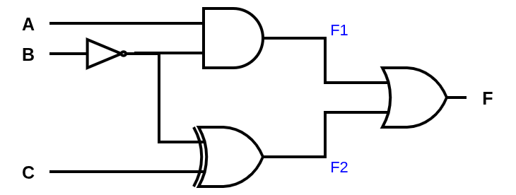
It is common in this kind of exercise to identify the intermediate outputs to make the analysis easier. They have already been marked in the diagram above as \(F1\) and \(F2\).
Solution
In the circuit above, we identify the intermediate outputs:
- \(F1 = A\bar{B}\)
- \(F2 = \bar{B} \oplus C = \bar{B} \bar{C} + BC\)
- \(F = F1 + F2\)
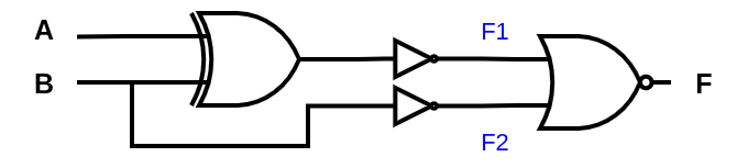
Exercise 2: Determine the logical expression for the output \(F\)
The circuit to analyze is the one in the figure below:
Solution
As in the previous exercise, we identify the intermediate outputs:
- \(F1 = \overline{A \oplus B} = \overline{\bar{A}B + A\bar{B}} = AB + \bar{A}\bar{B}\)
- \(F2 = \bar{B}\)
- \(F = \overline{F1 + F2} = \overline{AB + \bar{A}\bar{B} + \bar{B}} \)
Simplifying:
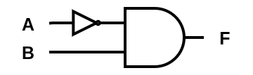
$$\begin{align*} F &= \overline{AB + \bar{A}\bar{B} + \bar{B}} \\ &= \overline{\bar{B}(1 + \bar{A}) + AB} \\ &= \overline{\bar{B} + AB} \\ &= \overline{\bar{B} + A} \text{ (Expanded absorption)} \\ &= \bar{A}B \text{ (De Morgan)} \end{align*}$$That is, the original expression of the circuit is equivalent to \(F = \bar{A}B\), which can be implemented with a single AND and an inverter, as shown in the diagram below:
Exercise 3: Draw and simplify the circuit of \(F = \overline{\bar{A}BC} + BC\)
Draw the circuit corresponding to the expression below. Make the drawing before simplifying the expression, and then simplify it to obtain a more efficient circuit.
$$F = \overline{\bar{A}BC} + BC$$
Solution
Before simplification, the circuit corresponding to the expression is:
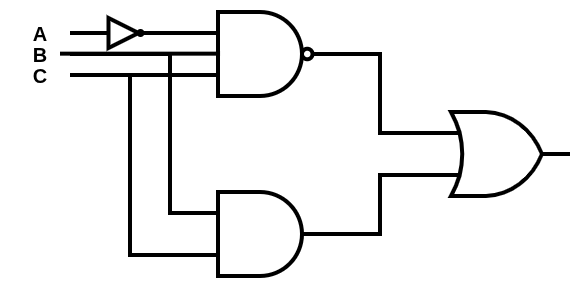
Simplifying the expression:
$$\begin{align*} F &= \overline{\bar{A}BC} + BC \\ &= A + \bar{B} + \bar{C} + BC \quad &\text{(De Morgan)} \\ &= A + \bar{B} + C + \bar{C} \quad &\text{(expanded absorption: } \bar{B} + BC = \bar{B} + C\text{)} \\ &= A + \bar{B} + 1 \quad &\text{(complement: } C + \bar{C} = 1\text{)} \\ &= 1 \quad &\text{(absorbing element: } X + 1 = 1\text{)} \end{align*}$$The expression is a tautology: the output is always 1, regardless of A, B and C. Representing this in a logic circuit, we have:
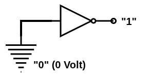
The figure above shows an inverter gate (NOT) with its input physically connected to ground (represented by the symbol of horizontal lines, which is equivalent to 0 volts). In Boolean algebra, this visually represents the postulate of negation: \(\bar{0} = 1\).
From a hardware engineering point of view, this is a real and indispensable circuit. In real chips (especially in CMOS technology), the inputs of logic gates that are not being used must never be left unconnected (“floating”). Loose pins act as small antennas that pick up electromagnetic noise from the environment, causing instability in the component. In addition, an input floating at an intermediate voltage can make the gate conduct current between the supply and ground, with excessive consumption and heating. By grounding the input (forcing a continuous “0”), the safety of the circuit is ensured and a constant, clean logic level “1” is obtained at the output.
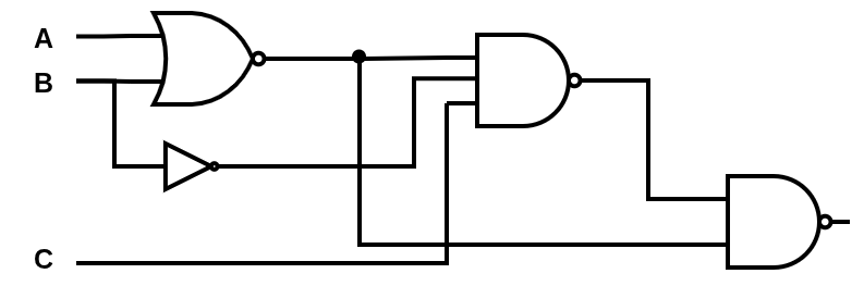
Exercise 4: Obtain the simplified expression for the output \(F\)
The circuit to analyze is the one in the figure below:
Solution
Identifying the intermediate outputs step by step:
Step 1:
- \(F_1 = \overline{A + B} = \bar{A}\bar{B}\) (NOR gate)
Step 2:
- \(F_2 = \overline{F_1 \cdot \bar{B} \cdot C} = \overline{\bar{A}\bar{B} \cdot \bar{B} \cdot C} = \overline{\bar{A}\bar{B}C}\) (using \(\bar{B} \cdot \bar{B} = \bar{B}\), idempotence)
- By De Morgan: \(F_2 = A + B + \bar{C}\)
Step 3:
- \(F = \overline{F_1 \cdot F_2} = \overline{F_1} + \overline{F_2}\)
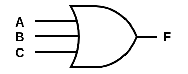
Applying Theorem 7 twice:
$$A + \bar{A}\bar{B}C = A + \bar{B}C \qquad \text{and then} \qquad B + \bar{B}C = B + C$$$$\boxed{F(A,B,C) = A + B + C}$$An apparently complex circuit (NOR + NAND + NAND) is equivalent to a simple 3-input OR gate! The equivalent circuit is shown below:
Python in practice #
Beyond the isolated examples, Python offers direct ways to explore Boolean algebra.
Bitwise operators: summary #
The main bitwise operators in Python and their Boolean equivalents, applied to integer values:
a, b = 0b1010, 0b1101  # 10 and 13 in decimal

print(f"a AND b  : {a & b:04b} = {a & b}")   # 1000 = 8
print(f"a OR  b  : {a | b:04b} = {a | b}")   # 1111 = 15
print(f"a XOR b  : {a ^ b:04b} = {a ^ b}")   # 0111 = 7
print(f"NOT a    : {~a}")                      # -11 (two's complement)
print(f"NOT a (4 bits): {~a & 0xF:04b}")     # 0101 = 5
Checking properties with Python #
def check_boolean(n_bits=4):
    """Checks the main properties for all n_bits-bit values."""
    limit = 2**n_bits
    mask = limit - 1  # e.g.: 0b1111 for 4 bits

    errors = []
    for a in range(limit):
        complement_a = (~a) & mask  # n_bits-bit complement of a

        # Idempotence
        if (a & a) != a: errors.append(f"Idem AND: a={a}")
        if (a | a) != a: errors.append(f"Idem OR: a={a}")

        # Complement
        if (a & complement_a) != 0: errors.append(f"Comp AND: a={a}")
        if (a | complement_a) != mask: errors.append(f"Comp OR: a={a}")

        # Double negation
        if ((~complement_a) & mask) != a: errors.append(f"Double neg: a={a}")

        for b in range(limit):
            # Commutative
            if (a & b) != (b & a): errors.append(f"Commut AND: a={a}, b={b}")
            if (a | b) != (b | a): errors.append(f"Commut OR: a={a}, b={b}")

            # De Morgan
            if (~(a & b) & mask) != ((~a | ~b) & mask):
                errors.append(f"De Morgan 1: a={a}, b={b}")
            if (~(a | b) & mask) != ((~a & ~b) & mask):
                errors.append(f"De Morgan 2: a={a}, b={b}")

    if errors:
        print("Errors found:", errors)
    else:
        print(f"All properties verified for {n_bits} bits!")

check_boolean(4)
# All properties verified for 4 bits!
Practical use: bitmasks in file permissions #
A classic use case of Boolean algebra in systems is permission control. In Unix/Linux systems, file permissions are stored as bits:
# Unix file permissions: the three rwx bits of a group (owner, group or others)
READ    = 0b100  # 4
WRITE   = 0b010  # 2
EXECUTE = 0b001  # 1

# A "read and execute" permission (no write):
permission = READ | EXECUTE  # 0b101 = 5

# Check whether it has read permission:
has_read = bool(permission & READ)    # True

# Add write permission:
permission = permission | WRITE            # OR: adds the bit → 0b111 = 7

# Remove execute permission:
permission = permission & ~EXECUTE          # AND with complement: clears the bit → 0b110 = 6

# Check whether the permission is exactly "read only":
has_exactly_read = permission == READ  # False: it also has write
These examples show that Boolean algebra is present in everyday programming tasks: from access control to data manipulation at the bit level.
Conclusion #
Boolean algebra is the language with which processors, memories and all digital circuits are designed. Mastering its operations, postulates, theorems and De Morgan’s laws is useful for:
- Understanding how processors execute logical and arithmetic operations
- Designing and optimizing digital circuits
- Correctly using bitwise operators in Python and other languages
- Understanding permission systems, network protocols and cryptography
The simplification exercises show that apparently complex expressions often reduce to very simple forms, and each simplification corresponds to a circuit with fewer gates.
In an upcoming article, we will explore systematic simplification methods: Minterms, Maxterms and Karnaugh Maps. They are tools that allow us to find the minimal form of any logic function in a methodical way.


